

Place holder for NASA Hypervelocity Return Missions.
Sentinel III system in photos

The Camera and Housing The housing for the camera, the anti-dew heater, the thermostat, and fan are all housed inside a PVC tube and toilet flange.
As packed for shipping. Stands approximately 0.5 meter tall.
Top shipping end removed reveals the camera and baffle.
The Rainbow L163VDC4P fisheye lens mounted on the camera body. Note the PVC stiffener rods with coax cable running through it..


ABMO Video Page
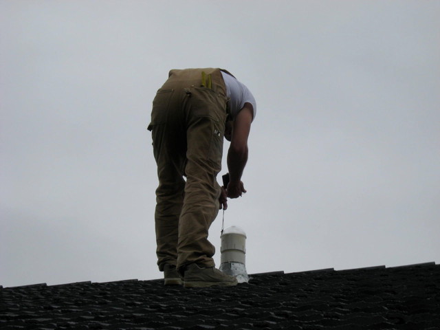
The observatory currently employs only one camera with a fish eye lens. The camera is mounted through the roof; it replaced a cap over a former aluminum chimney from a living room gas fireplace. The outside finger joints are sealed with silicon caulking preventing any water from entering the attic. In the photo below a friend, Brent, shoots in true north with compass as I rotated the camera’s base from within the attic.
The lower end of the camera housing is inside the attic. I installed an AC outlet right next to it to power the camera and anti-dew heater. The black wire is the coax that carries the 1 Vp-p raw video signal down to the amplified video distribution box.

The installment is complete and ready to observe.

The raw video signal is sent from the rooftop down a coax to an amplified video distribution box (See below).

From the video splitter the video is then piped to a computer running the Python language program that came with the Sandi National Laboratories Sentinel camera. Since the original program was written in Python it can run on any operating system. The Sentinel software has been running flawlessly for three years on a very old, very slow, and very limited memory refurbished laptop running Linux. This software uses an external frame grabber as shown below.

The video break out box also sends raw video to a second computer running the latest version of the Sentinel system. Unfortunately the next generation of the Sentinel system software is a Windows only – compiled software. It requires an internal PCI slot for an internal frame grabber. The board is a ImpactVCB model 188 board that comes with Hauppauge WinTV version 5.9G installation software.

The software is in early beta testing stage and bugs are being suppressed with each beta version. Eventually the software will automatically ftp all overnight captures to New Mexico where the files will processed and analyzed for each observer. This feature is not yet implemented.
A third output of the video break out box is sent to a external Canopus ADVC-110 video to digital converter. The digital output from the ADVC is then sent by firewire to the computer where the UFOCapture program detects the meteors. To see an informative video about the ADVC-110 go here – It will take you to the YouTube site and play the video.
More to come…
ABMO Radio Page
ABMO Radio Page
Latest radio meteor echoes from W Kelowna, B.C.
Highest none shower counts are at local sunrise and the lowest are at sunset.
Introduction
The observatory is located in West Kelowna and it uses the forward scatter technique of meteor echo detection. The receiver is tuned to TV channel 4’s video carrier frequency (negative offset) at 64.240 MHz. The echoes are from the video carriers of the two station listed below:
| Station | QTH | Bearing | km | kW |
| CITL-TV | Lloydminster, AB | 56 | 770 | 130 |
| CBKT-1 | Moose Jaw, SK | 81 | 975 | 100 |
When a meteor has the proper geometry between the transmitting TV station and the receiving station an echo is produced as the receiver as the signal is reflected off the ionized plasma produce while the meteor ablates in the earth’s upper atmosphere. The ionization usually occurs between 110 down to 60 km up, thus giving a radio coverage out to about 1400 km radius of the receiver.
The station consist of an Icom PCR-1000 to a seven element log periodic antenna. The antenna is installed in the attic and pointing 70 degrees or towards the northeast. A fifty foot piece of RG-58 coax connects the antenna to the receiver. No pre-amps are used. The PCR-1000 is a software controlled receiver; a small black box with only an on and off switch on the front.

In the back of the PCR-1000 are:
BNC Antenna connector, a ground post, DC Input, Audio Out, a RS-238 connector for communication with the computer, and a special 9600 bps audio filtering bypass for high speed digital packet radio used on amateur built satellites (AMSAT).

During the major showers the observatory employs several different programs on several different computers on the LAN. Audio is split off the PCR-1000 as seen above (Y-adapter audio out) and shared among the computers during the showers. Alternatively, I use a second receiver, the ICOM R-8500 that runs in parallel with the PCR-1000 but on a different frequency, and run the audio from it to separate computer for real time analysis.
If a shower is predicted to show once in a lifetime activity I will also run an ICOM IC-746 transceiver. I usually devote the IC-746 to listening to 40.530 MHz, the US SNOTEL meteor system. SNOTEL has two master stations (transmitters) located in Utah and in Idaho which put in strong meteor burst signals into BC.

The software does the actual detection, counting, data filing and display work. Software in use includes Spectrum Lab, mAnalyzer, HROfft, all capable Windows programs. Watch for a software discussion in the Radio Detection Basics in the Radio Methods section of the site. In addition to the above programs the observatory runs Janalyzer and a self written code. Which program is used is dependent on the subject understudy or nature of the shower.
Note: I do run the above programs on both Windows XP and on Linux machines. To see how I run it on a Linux machine please go to the RMOB site and read the article. Janalyzer is written in Java so is cross platform ready.
I set my software to output data at ten minute periods and on the hour. Depending on what software is running, duration for each 10 minute and hourly interval is recorded along with signal strengths in several bins of approximately 10 dB, 20 dB, 30 dB, and greater than 30 dB. Total time in seconds per period for each power level is also recorded.
A FFT spectrogram for each five minute period is ftp to an external site as well as saved on a local hard drive for study later or for the correlation with video fireballs
To be continued…
Student/Teacher Resources Page
To analyze meteor data with UFO Capture, refer to the instructions found under Video Analysis/Student UFO2 User Guide.
Download our Teacher Reference Documents (in PDF form) at our Downloads\References Section. These are collected from NASA, European Space Agency and other public sources.
There are three pages or more of files there: to switch pages click on the blue double arrows at the top right side of the page: “Page 1 of 3 >>” .
To download, put a checkmark in the boxes beside the files you want and hit “continue”. That should bring up a Download button, click that and it will download the PDF document into another browser window. (Note that some security filters may block this button, and show “[ad]” instead. To check, hover over that, you should see (for example) http://www.bcmeteors.net/downloads/finish/36/142.html, where 142 was the article number. Click on that [ad] icon to download it).
School District #27 (Cariboo-Chilcotin)
School District #27, in partnership with the Prince George Astronomical Society, provided Tatla Lake Elementary/Jr. Secondary School as a site for an AllSky Camera.
Welcome Tatla Lake School
A special welcome to the Tatla School and it’s new video meteor camera! We look forward to working with you.
Preparation for calibrating a Sentinel Camera
Steps to take prior to calibrating a Sentinel Camera
Flesh out – PLACEHOLDER ONLY!
Put the procedure here.
- Make long exposure after each capture… TIF format
- Use GIMP, Paint, PhotoShop or other image processing program and push the brightness and contrast
- After photo brings out the hidden starts run a planetarium program. Looking south, elv 90, fov 180.
- Match the stars noting pixel x/y on photo and az/el on the planetarium.
- run python program calpos.py This produces a personalized correction file that will be used for triangulation. (See Ken’s pdf on the process)
RASC Prince George Centre Observatory

RASC Prince George Centre Observatory (aka Prince George Astronomical Society) is located on Tedford Road in Prince George. It is a nonprofit organization dedicated to the advancement of astronomy and science in Prince George and the neighbouring Northern Canadian communities.
RASC Prince George Centre employs three methods of meteor detection
DETECTION USING AN FM CARRIER FREQUENCY

The RASC Prince George Centre has implemented a meteor detection project using information obtained from the Sky Scan Science Awareness Project and a program called Radio-SkyPipe. Two FM automobile radios tuned to 98.7 MHz, a Yagi antenna, and a Quadrifilar Helicoidal antenna, enable us to collect data and present it here in graph form.


DETECTION USING A TV CARRIER FREQUENCY
The RASC Prince George Centre Observatory has associated itself with the International meteor detection organization called Radio Meteor Observatories On Line. Using the programs Spectrum Lab and Colorgramme RMOB lab, along with an ICOM IC-PCR1000 receiver tuned to Channel 3 video carrier frequency 61.240 MHz, we are able to collect data and present it here. Meteor activity on the left is in graph form for a 24 hour period. Data in the right hand box accumulates during the month and is colour based with blue signifying zero activity. Colours approaching red signify increased activity.

DETECTION USING AN ALLSKY VIDEO SYSTEM

The following image is the latest real time capture from the AllSky camera installed at the RASC Prince George Centre Observatory. This camera has a 180 degree field of view. North is up, West is to the right.

Student UFO2 User Guide
The Sonotaco.com site provides you with the latest capture and analysis software. The basic requirements are:
1) UFOCaptureV2 V2.22 to capture the data. Registration of this program is required after 30 days and the cost is 18900 Japanese Yen. Use this currency converter to determine the cost in your currency. You’ll also need the Users Manual. It is offered in an html and zipped format.
2) UFOAnalyzer V2 V2.28 to analyze the data. This is a free program. Provided in a pdf and zipped format, the Users Manual is essential to understanding this program. If you are a BC camera operator, download and install the Map of Canada (West) file. Scroll down to the bottom of the page to locate it. Extract the file to the UA2 root directory.
3) UFOOrbitV2 V2.25 to determine the meteor’s orbit. This is a free program. The Users Manual for this utility is offered in a pdf and zipped format.
The BBS Forum is also a good source of user information. You don’t need to speak or read Japanese 🙂
For those people that simply want to analyze the data, follow steps 2 and 3, and then do the following:
4) Download the contents of the UProfiles for UFO2 operators folder found in the Data Downloads/Video Data Downloads section and install the contents into the PROF folder of UA2.
5) To analyze individual captures, select a file found in the Data Downloads/Video Data Downloads section from any of the observatories using UFO2. At the moment, they are RASCPG, RDL, Shane, and Tatla. Download and extract the files into your directory. How you set up your directory is up to you. Use UA2 to analyze the data and plot a ground map.
6) To analyze common captures, you will download and analyze the files from Data Downloads/Video Data Downloads/Common Captures individually (don’t forget to select the profile for the site you are working with)…but you will perform one final step involving the use of Paint.NET. You will have saved the UA2 ground map from each site analysis. Using the Paint.NET tutorial, overlay the ground maps to determine the intersecting point.
7) When you have determined the intersecting point, email your results for confirmation to the administrator of this site. Your files will include the .XML and ground map files for each of the sites you worked with, as well as the overlay map from Paint.NET. Once your data is confirmed with other site users, it will be posted in the Video Results and Papers section and forwarded on to the Coordinator of the Canadian Fireball Reporting Centre at the University of Calgary.